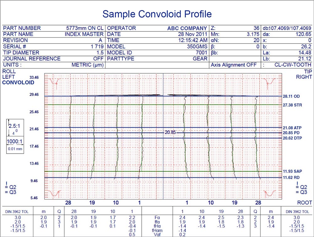
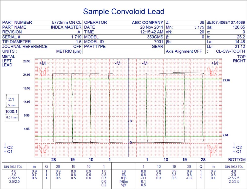
Convoloid® is a patented, non-involute conjugate gear tooth form. A convex addendum meshes with a concave dedendum, and the gears are made on the hobbing, shaping and grinding machines you already own.
The involute gear tooth form has dominated engineering for over two centuries. It's been studied, refined, and optimized to near perfection, and the remaining gains come mostly from materials and finishing, not from the tooth form.
New materials, coatings, and surface finishing help at the margins. But the fundamental geometry hasn't changed. Convex meets convex, with maximum Hertz contact stress built in.
Convoloid changes the equation. A computer-optimized tooth form where convex meets concave, lowering contact stress while remaining compatible with the gear-cutting and inspection machines on your floor.
The same physics that defines Convoloid's tooth form shows up in published rating analysis and in physical test. Every figure below is compared against an equivalent involute: same center distance, ratio, materials and heat treatment, face width, load and lubrication.
Rated per AGMA/ISO against an equivalent involute baseline, Convoloid shows 20–35% higher torque capability, published in AGMA 11FTM19 (Berlinger & Colbourne, 2011). The advantage is greatest in balanced designs with design freedom: face-width to center-distance ratios of about 0.2 and up, helix angles of 20–30° and higher ratios.
When a design is constrained to match an involute's power and stress levels, analysis shows the Convoloid gearbox can be up to about 20% smaller in enclosed volume and lighter. An analytical redesign of the Micon 108 wind gearbox came out 20.6% smaller in volume. (The unit DOE/NREL tested was a same-size retrofit, not this redesign.)
Convex-meets-concave contact lowers surface (Hertz) stress and root bending stress. In DOE/NREL gearbox testing at 200–240% of rated load, early micropitting on the Convoloid gears self-arrested and contact improved, while the involute's micropitting progressed to the end of the test.
Convoloid's inventor walks through what makes the tooth form different from the involute, and why that matters for power density, weight and life. It's the quickest way to understand the technology.
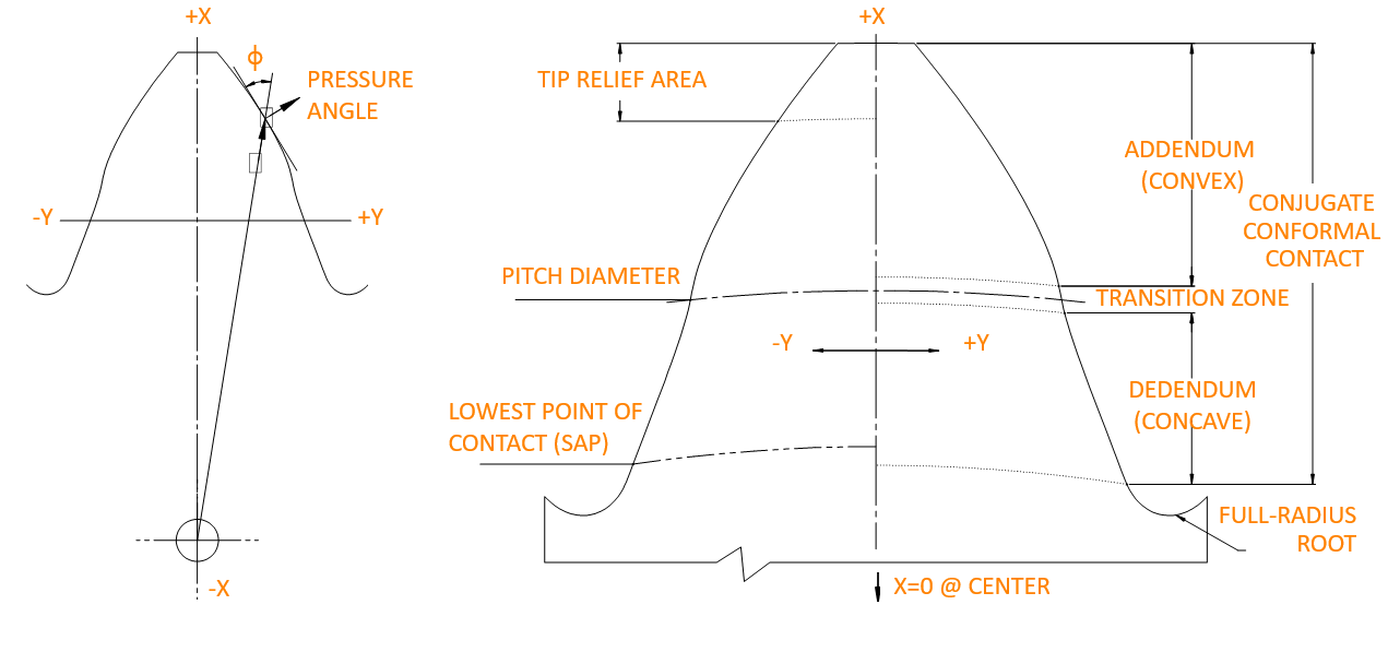
Each Convoloid tooth has a characteristic S-curved profile. The dedendum (below pitch line) is concave; the addendum (above pitch line) is convex. This creates the conformal, lower-stress contact.
Unlike involute gears, Convoloid has no base circle, eliminating undercut constraints on small pinions. More design freedom, optimized for each application via computer point-by-point calculation.
Convoloid is conjugate through most of the addendum and dedendum, with contact that accurately follows the Euler-Savary equation. Nearly constant relative radii of curvature maintain consistent Hertz stresses across the entire flank. No stress spikes.
Convoloid is made on existing gear-cutting, grinding and inspection equipment at standard cycle times, and manufacturing sequences mirror involute processes. The transition is a design change, not a capital investment.
These aren't illustrations. Every gear below is generated from the Convoloid® basic rack (convex addendum, concave dedendum, S-shaped transition through the pitch line) using the same rolling motion a hob uses on the shop floor. The amber dashed curve is the true path of contact; glowing points are live tooth contact.
Watch a standard 20° involute tooth become a Convoloid tooth. The flank turns into an S: a convex addendum above the pitch line, a concave dedendum below it, joined by a smooth transition where every junction is tangent.
The amber comb plots curvature along the flank. It flips sign at the pitch line, so a convex flank always meets a concave flank.
A 13-tooth pinion driving 27 teeth. With no base circle there's no undercut limit, and the contact ratio stays above 1.0, so spur Convoloid gears run smoothly.
The same transverse Convoloid profile swept along a 22° helix, in opposite hands. Contact lines stay unbroken across the full face width.
A 30° double helix cancels axial thrust. It's built for the heavy-duty drives (wind, mining, marine) where power density matters most.
A 21-tooth sun, three 15-tooth planets and a 51-tooth internal ring. The ring is generated to match the planet, so internal meshes get the same convex-to-concave contact.
This is the rack that defines the whole Convoloid system. Every gear above is generated from it, which is why Convoloid can be cut on existing CNC hobbing and grinding machines.
At the mesh, a convex addendum rolls against a concave dedendum. The two curves nest instead of touching at a single sharp point, so the load spreads over a wider band and contact stress drops.
The differences between a Convoloid tooth and its involute equivalent are subtle, but they produce powerful results. Manufacturing sequences, tolerances and material allowances closely follow involute practice.
Hobbing, shaping, skiving, form grinding and threaded-wheel grinding all apply, at standard cycle times, and hob costs are comparable to special involute cutters. Shaving is not recommended. Pinion and gear need separate cutters. Because the tooth is described digitally, it is compatible with the CNC gear manufacturing and inspection equipment in use worldwide.
Inspected on standard CNC gear checkers to AGMA, ISO, DIN and JIS quality grades. Accuracy classes use the same parameters, limits and identification. Lead modification, crowning, tip relief and root relief can all be designed in and measured. Center-distance tolerance practice is ±0.005 × transverse module.
Rating modifiers and tolerances from world-recognized standards apply directly:
| Analysis | AGMA | ISO |
|---|---|---|
| Contact & bending | 2001/2101, 6011, 6013, 6015 | 6336, 13593 |
| Tolerances | 2015-2 | 1328-1 |
| Inspection | 915 | 10064 |
| Scuffing | 925 | 13989, 14635-1 |